The Wave Transformer
Hey there, friendo!
Congrats on the purchase of The Wave Transformer Asymmetrical Multi-Differential Wave Transfiguration Device.
The Wave Transformer is a vintage-voiced voltage-controlled oscillator with over 8 octaves of accurate pitch tracking. It has 7 simultaneous wave outputs, including a unique Complex output.
The Transform control morphs from a basic waveform through many strange iterations into a complex, gnarled mass of audio mutations at the Complex output. You can yield countless variations on these permutations by combining this novel circuit with Hard Sync, Soft Sync, Linear FM and Exponential FM. Additionally, you can mute the source waveform to use the circuit as a harmonic gate/VCA. If that is not enough, there is a Shape Insert that allows you to transform external oscillations and modular-level audio sources.
An extra special thanks to Angela Kolenc, Jamie Stillman, Julie Robbins, Luke Zollinger, Karl Vorndran and Jon Sonnenberg. Without your support, none of this would be possible.
Joshua Kolenc
Module designer and manual author
Warnings
ELECTRICAL HAZARD! IMPROPER INSTALLATION OR HANDLING MAY RESULT IN ELECTROCUTION OR DAMAGE TO YOUR MODULE, EURORACK CASE OR OTHER MODULES. ALWAYS BE CERTAIN TO POWER OFF AND UNPLUG YOUR EURORACK CASE OR POWER SUPPLY BEFORE INSTALLING A MODULE. ALSO, PLEASE BE CERTAIN TO COVER ANY EMPTY RACK SPACES WITH BLANK PANELS.
HIGH SIGNAL LEVELS! THIS DEVICE IS CAPABLE OF PRODUCING MODULAR SIGNAL LEVELS OVER +/-10 VOLTS. PLEASE USE CARE WHEN OPERATING THIS EQUIPMENT, AS HIGH SIGNAL LEVELS CAN DAMAGE YOUR AUDIO EQUIPMENT OR YOUR HEARING!
EARTHQUAKER DEVICES DOES NOT IMPLY NOR ASSUME ANY RESPONSIBILITY FOR HARM TO ANY PERSON OR DAMAGE TO ANY DEVICE OR OBJECT AS A RESULT OF THE USE OF THIS MODULE.
FCC Compliance
THIS DEVICE COMPLIES WITH PART 15 OF THE FCC RULES. OPERATION IS SUBJECT TO THE FOLLOWING TWO CONDITIONS: (1) THIS DEVICE MAY NOT CAUSE HARMFUL INTERFERENCE, AND (2) THIS DEVICE MUST ACCEPT ANY INTERFERENCE RECEIVED, INCLUDING INTERFERENCE THAT MAY CAUSE UNDESIRED OPERATION. CHANGES/ MODIFICATIONS NOT APPROVED BY EARTHQUAKER DEVICES LLC COULD VOID THE USER’S AUTHORITY TO OPERATE THE EQUIPMENT. THIS EQUIPMENT HAS BEEN TESTED AND FOUND TO COMPLY WITH THE LIMITS FOR A CLASS A DIGITAL DEVICE, PURSUANT TO PART 15 OF THE FCC RULES. THESE LIMITS ARE DESIGNED TO PROVIDE REASONABLE PROTECTION AGAINST HARMFUL INTERFERENCE WHEN THE EQUIPMENT IS OPERATED IN A COMMERCIAL ENVIRONMENT. THIS EQUIPMENT GENERATES, USES, AND CAN RADIATE RADIO FREQUENCY ENERGY AND, IF NOT INSTALLED AND USED IN ACCORDANCE WITH THE INSTRUCTION MANUAL, MAY CAUSE HARMFUL INTERFERENCE TO RADIO COMMUNICATIONS.
Tech Specs
- Horizontal pitch (HP)
-
20HP
- Max Depth
-
1 inch/25.4 mm
- Current Draw
-
90 mA max from the +12v rail
-
90 mA max from the -12v rail
Standard 10-pin Eurorack power connector with a marking to notate the negative pins
Skiff friendly – protrudes less than 1 inch (25.4 mm) behind the panel with the power header installed
We recommend the use of a high quality, low noise power supply.
Installation
- Power off and unplug your Eurorack case or power supply and locate 20HP of empty space within your system.
- Connect the 10-pin end of the included ribbon cable to the power pin header on the back of your module so the red stripe on the cable is oriented towards the words “Red Stripe” that are printed on the circuit board. Connect the 16-pin end of the ribbon cable to the bus board of your Eurorack case according to the specifications of your case or bus board manufacturer. Be certain that you have oriented your cable properly or you may cause damage to your module or system.
- Affix the module to your rails with mounting screws that are compatible with your case and then cover any remaining open space with blank panels.
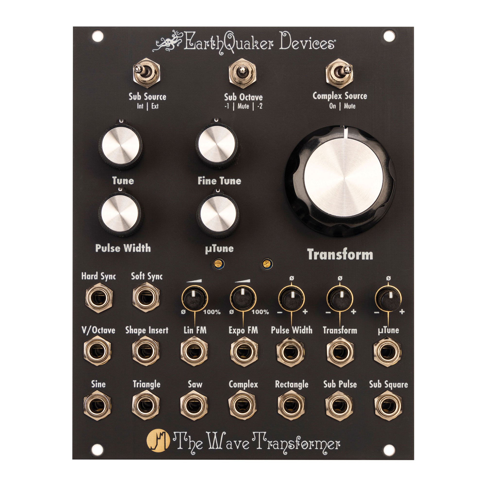
Panel Controls
Sub Source switch:
Selects either the internal oscillator or the signal patched into the Shape Insert jack for use in generating sub octaves. This control affects the Complex, Sub Pulse and Sub Square outputs. Leave this set to “Int” unless you are tracking an external source.
Sub Octave switch:
Selects between 1 octave down, 2 octaves down or muting the sub octaves. This control affects the Complex and Sub Square outputs. The Sub Pulse output is unaffected by this control, as it is fixed to 1 octave down.
Complex Source switch:
Selects between muting and unmuting the source wave for the Complex output.
Leaving the source wave unmuted allows you to hear the waveform morph from the original wave through multiple iterations until it reaches maximum harmonic complexity.
Muting the source waveform means that the Complex output will be silent if the Transform panel control is fully counterclockwise, and no CV is present at the Transform CV input. This allows the Transform circuit to act as a harmonic gate/VCA. It will go from silence to increasing in volume and harmonic complexity as the panel control or CV input increase.
Tune control:
Coarse control of the pitch of the oscillator, spanning approximately 7 octaves.
Fine Tune control:
Fine control of the pitch of the oscillator, spanning a little more than 1 octave.
µTune (Micro Tune) control:
Ultra fine control of the oscillator, spanning approximately 25 cents.
Pulse Width control:
Varies the Pulse width of the Rectangle output between 0% and 100%. At 0% or 100% Pulse Width, the Rectangle output is silent.
Transform control:
Morphs the Complex output from a triangle wave through multiple iterations into a strange and harmonically complex waveform, using an asymmetrical multi-differential audio transmutation circuit.
It will vary from a simple waveform to a silhouette of your cat watching you as you react to a “present” that it left for you on the counter. No, seriously.
Inputs
Hard Sync input:
Accepts +/-5 volts. Uses the incoming signal to reset the phase of the oscillator. This input will work best with pulses. It can use either positive pulses, negative pulses, or bi-polar pulses. The positive pulses and negative pulse will reset the oscillator to different points in its phase. Using bipolar pulses will alternate between resetting the oscillator to the two different phases. Incoming pulses will force the oscillation period to be tuned to integral multiples of the incoming signal. Sync tracking is highly dependent on the characteristics and frequency of the incoming signal, as well as the frequency of The Wave Transformer.
Soft Sync input:
Accepts +/-5 volts. Pulses at this input cause the upper peak of the triangle wave to prematurely change direction, causing the oscillation period to be a multiple of the pulse width of the incoming signal. Sync tracking is highly dependent on the characteristics and frequency of the incoming signal, as well as the frequency of The Wave Transformer.
V/Octave input:
Accepts traditional volt/octave CV to control pitch. It can also accept up to -10 volts to slow it down to as low as .12Hz for LFO duty. Over 8 octaves of accurate pitch tracking starting at A-1 (13.75Hz).
Shape Insert input:
Accepts +/-5 volts. Allows the insertion of another waveform or modular-level signal to be mutated by the Transform circuit. The new waveform will change the results heard at the Complex output. The sub-octave circuit can track the signal that is inserted if you set the Sub Source switch to “Ext”. Otherwise, the Complex output will have a mixture of harmonics derived from the external audio and sub-octaves derived from the internal oscillator. Lots of strange and interesting results can be achieved with creative combinations and cross-modulations with external sources.
Note:
The original waveform inserted into this input will only be heard if Complex Source is set to “On”, and the Transform control is fully counterclockwise with no CV present at the Transform CV input.
Lin FM input:
Accepts +/-5 volts audio signals. Allows linear frequency modulation, where an increase or decrease in control voltage respectively increases or decreases the pitch of the oscillator in a manner that has a linear relationship to the incoming voltage.
The input is AC coupled to block DC signals in order to reduce any pitch offset during use of frequency modulation.
This input is accompanied by an attenuator that is located above the input jack. The incoming signal is fully attenuated when the trimmer is counterclockwise and passes through unaffected when the trimmer is fully clockwise.
Expo FM input:
Accepts +/-10 volts. Allows linear frequency modulation, where an increase or decrease in control voltage respectively increases or decreases the pitch of the oscillator in a manner that has an exponential relationship to the incoming voltage. That is to say that with each volt of increase at the input the audio frequency will double.
The input is DC coupled to allow the use of voltage offsets, audio rate signals, and everything in between.
This input is accompanied by an attenuator that is located above the input jack. The incoming signal is fully attenuated when the trimmer is counterclockwise and passes through unaffected when the trimmer is fully clockwise.
Pulse Width input:
Accepts +/-5 volts. Allows control or the pulse width of the Rectangle output from 0-100% duty cycle. Pulse width can be modulated with DC control voltages and audio signals.
Note:
Settings of 0% or 100% will result in silence at the Pulse Width output.
This CV input is added to the Pulse Width panel control. Use the panel control to set the default pulse width from which you would like to modulate.
This input is accompanied by an inverting attenuator that is located above the input jack. When the associated trimmer is fully clockwise, the CV passes unchanged to be mixed with the panel control. When the trimmer is in the noon position, the CV is fully attenuated. When the trimmer is fully counterclockwise, the CV is inverted before mixing with the panel control to result in subtraction.
Tip:
The pulse width can be modulated to create silence when you do not wish to hear a note, bypassing the need for a VCA in some instances.
Transform CV input:
Accepts 0-5 volts. Allows control of the Transform circuit. This CV input is added to the Transform panel control. Use the panel control to set the default Transformation from which you would like to modulate.
This input is accompanied by an inverting attenuator that is located above the input jack. When the associated trimmer is fully clockwise, the CV passes unchanged to be mixed with the panel control. When the trimmer is in the noon position, the CV is fully attenuated. When the trimmer is fully counterclockwise, the CV is inverted before mixing with the panel control to result in subtraction. Transform can be modulated with DC control voltages and audio signals.
Tip:
Switching the Complex Source panel control to “Mute” will allow the Transform circuit to act as a harmonic gate/VCA, where the volume and harmonic complexity will increase as the CV increases at this input. The effects will be relative to the setting of the panel control, with the signal muted when the panel control is fully counterclockwise and no voltage is present at the CV input.
µTune CV input:
Accepts +/-10 volts. This is an exponential CV input that allows precise modulation of the oscillator pitch. An increase in voltage of 10 volts will increase the pitch by around 7 semitones. This input can be used to sequence precise pitch bends, adding pitch instability with a random voltage source, or sequencing tiny changes in pitch for drone or microtonal music.
This CV input is added to the Tune and Fine Tune panel control. Use the panel controls to set the default pitch from which you would like to modulate.
This input is accompanied by an inverting attenuator that is located above the input jack. When the associated trimmer is fully clockwise, the CV passes unchanged to be mixed with the panel control. When the trimmer is in the noon position, the CV is fully attenuated. When the trimmer is fully counterclockwise, the CV is inverted before mixing with the panel control to result in subtraction. µTune can be modulated with DC control voltages and audio signals.
Outputs
Sine output:
+/-5 volts. The most basic waveform, it sounds smooth and clean, and is made up of only the fundamental frequency.
Triangle output:
+/-5 volts. A bit pointier than the Sine wave, the Triangle wave has a little bit more buzz to it and contains a combination of the fundamental frequency and odd order harmonic frequencies that taper off rather quickly.
Saw output:
+/-5 volts. This is a negative ramp saw (ramp down). It has an even buzzier sound than the triangle and contains a mixture of the fundamental frequency and both even order and odd order harmonic frequencies.
Complex output:
Up to +/-10 volts. This strange and novel output varies between a simple waveform (triangle, unless you patch a signal into the Shape Insert jack) and a complex transformation of the harmonic structure of the original waveform. It contains a unique mixture of the fundamental frequency, odd order harmonics, even order harmonics and subharmonics. The Sub Octave panel control will determine whether the sub harmonics are derived from one octave down, two octaves down, or are muted altogether.
The ratios of the harmonic/subharmonic content and structure will mutate as the Transform control or associated CV is changed. Unlike the other outputs, this output also varies in amplitude in a linear relationship with the panel control and/or incoming CV.
Patching other wave outputs or external signals into the Shape Insert jack will change what is present at this output.
Using the Complex Source panel control to mute the source wave will cause the Complex output to be silent if the Transform panel control is fully counterclockwise, and no CV is present at the Transform CV input. This allows the Transform circuit to act as a harmonic gate/VCA. It will go from silence to increasing in harmonic complexity as the panel control or CV input increase.
Rectangle output:
+/-5 volts. The pulse width of this waveform is dependent upon the Pulse Width panel control and its associated CV input. When there is no CV present, and the panel control is set to noon, a 50% duty cycle (Square) waveform is achieved. When in this configuration, it has a rich and buzzy sound that is comprised of the fundamental frequency and odd order harmonics that roll off more slowly than with the triangle wave. Varying the Pulse Width changes the harmonic content of this output, reducing odd order harmonics, and in some settings, increasing even order harmonics.
Modulating the Pulse Width CV input can produce a lot of interesting motion and harmonic variation.
Sub Pulse output:
+/-5 volts. 25% duty cycle sub octave signal that is 1 octave lower than the source signal. The source signal is selected by the Sub Source switch. When set to „Int“, sub octave is derived from the internal oscillator. When set to „Ext“, the sub octave is derived from the signal that has been patched to the Shape Insert jack.
This output is fixed at 1 octave down and does not respond to changes to the Sub Octave panel control.
Note:
We purposely used an “unprocessed” version of this output, rather than one that was reshaped using a comparator circuit. It has a sound that is more raw and aggressive.
Sub Square output:
+/-5 volts. A sub octave square wave that is either 1 or 2 octaves down from the source signal, depending on the Sub Octave setting. The source signal is selected by the Sub Source switch. When set to “Int”, sub octave is derived from the internal oscillator. When set to “Ext”, the sub octave is derived from the signal that has been patched to the Shape Insert jack.
Note:
As is the same with the Sub Pulse, we purposely used an “unprocessed” version of this output, rather than one that was reshaped using a comparator circuit. It has a sound that is more raw and aggressive.
Warranty
We will fix any of our devices for as long as we are in business. There is never a charge unless the circuit board needs to be replaced due to user damage such as a failed non-factory repair, incorrect power supply, reverse voltage, modification, water damage, etc. Please visit www.earthquakerdevices.com/warranty for any questions or to initiate a warranty claim.