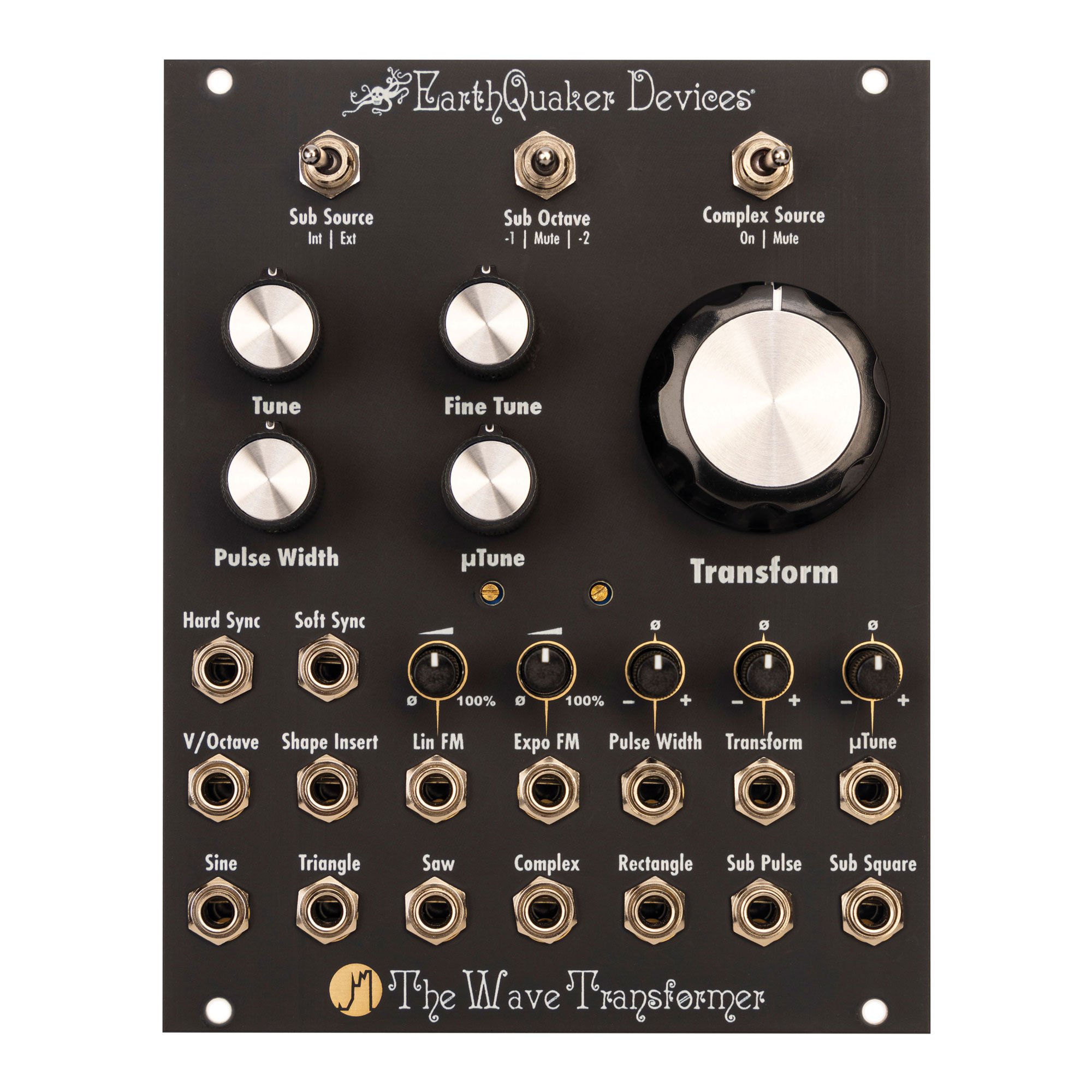
The Wave Transformer
Hey there, friendo!
Congrats on the purchase of The Wave Transformer Asymmetrical Multi-Differential Wave Transfiguration Device.
The Wave Transformer is a vintage-voiced voltage-controlled oscillator with over 8 octaves of accurate pitch tracking. It has 7 simultaneous wave outputs, including a unique Complex output.
The Transform control morphs from a basic waveform through many strange iterations into a complex, gnarled mass of audio mutations at the Complex output. You can yield countless variations on these permutations by combining this novel circuit with Hard Sync, Soft Sync, Linear FM and Exponential FM. Additionally, you can mute the source waveform to use the circuit as a harmonic gate/VCA. If that is not enough, there is a Shape Insert that allows you to transform external oscillations and modular-level audio sources.
An extra special thanks to Angela Kolenc, Jamie Stillman, Julie Robbins, Luke Zollinger, Karl Vorndran and Jon Sonnenberg. Without your support, none of this would be possible.
Joshua Kolenc
Module designer and manual author
Warnings
ELECTRICAL HAZARD! IMPROPER INSTALLATION OR HANDLING MAY RESULT IN ELECTROCUTION OR DAMAGE TO YOUR MODULE, EURORACK CASE OR OTHER MODULES. ALWAYS BE CERTAIN TO POWER OFF AND UNPLUG YOUR EURORACK CASE OR POWER SUPPLY BEFORE INSTALLING A MODULE. ALSO, PLEASE BE CERTAIN TO COVER ANY EMPTY RACK SPACES WITH BLANK PANELS.
HIGH SIGNAL LEVELS! THIS DEVICE IS CAPABLE OF PRODUCING MODULAR SIGNAL LEVELS OVER +/-10 VOLTS. PLEASE USE CARE WHEN OPERATING THIS EQUIPMENT, AS HIGH SIGNAL LEVELS CAN DAMAGE YOUR AUDIO EQUIPMENT OR YOUR HEARING!
EARTHQUAKER DEVICES DOES NOT IMPLY NOR ASSUME ANY RESPONSIBILITY FOR HARM TO ANY PERSON OR DAMAGE TO ANY DEVICE OR OBJECT AS A RESULT OF THE USE OF THIS MODULE.
THIS DEVICE COMPLIES WITH PART 15 OF THE FCC RULES. OPERATION IS SUBJECT TO THE FOLLOWING TWO CONDITIONS: (1) THIS DEVICE MAY NOT CAUSE HARMFUL INTERFERENCE, AND (2) THIS DEVICE MUST ACCEPT ANY INTERFERENCE RECEIVED, INCLUDING INTERFERENCE THAT MAY CAUSE UNDESIRED OPERATION. CHANGES/ MODIFICATIONS NOT APPROVED BY EARTHQUAKER DEVICES LLC COULD VOID THE USER’S AUTHORITY TO OPERATE THE EQUIPMENT. THIS EQUIPMENT HAS BEEN TESTED AND FOUND TO COMPLY WITH THE LIMITS FOR A CLASS A DIGITAL DEVICE, PURSUANT TO PART 15 OF THE FCC RULES. THESE LIMITS ARE DESIGNED TO PROVIDE REASONABLE PROTECTION AGAINST HARMFUL INTERFERENCE WHEN THE EQUIPMENT IS OPERATED IN A COMMERCIAL ENVIRONMENT. THIS EQUIPMENT GENERATES, USES, AND CAN RADIATE RADIO FREQUENCY ENERGY AND, IF NOT INSTALLED AND USED IN ACCORDANCE WITH THE INSTRUCTION MANUAL, MAY CAUSE HARMFUL INTERFERENCE TO RADIO COMMUNICATIONS.
Tech Specs
- Horizontal pitch (HP)
-
20HP
- Max Depth
-
1 inch/25.4 mm
- Current Draw
-
90 mA max from the +12v rail
-
90 mA max from the -12v rail
Standard 10-pin Eurorack power connector with a marking to notate the negative pins
Skiff friendly – protrudes less than 1 inch (25.4 mm) behind the panel with the power header installed
We recommend the use of a high quality, low noise power supply.
Installation
- Power off and unplug your Eurorack case or power supply and locate 20hp of empty space within your system.
- Connect the 10-pin end of the included ribbon cable to the power pin header on the back of your module so the red stripe on the cable is oriented towards the words “Red Stripe” that are printed on the circuit board. Connect the 16-pin end of the ribbon cable to the bus board of your Eurorack case according to the specifications of your case or bus board manufacturer. Be certain that you have oriented your cable properly or you may cause damage to your module or system.
- Affix the module to your rails with mounting screws that are compatible with your case and then cover any remaining open space with blank panels.
Frequently Asked Questions
“Why am I getting silence at the Complex output?”
The Complex output will produce silence if the Complex Source switch is set to “Mute” and either the Transform knob is fully counterclockwise or the Transform CV input is receiving negative control voltage. Either change the position of the Complex Source switch, increase the Transform control, ensure that your control voltage is positive, or check to make sure that the attenuverter for the Transform CV input is set to a clockwise position.
“Why am I getting silence at the Rectangle Output?”
The Rectangle output will produce silence when the Pulse Width knob is set to near either fully counterclockwise or fully clockwise, or your control voltage source is pushing the parameter to those ranges. This is the intended operation, and it is useful for when the user would like to strategically add silence through modulation of the CV input. Simply adjust the position of the Pulse Width knob or adjust the control voltage or attenuation and the control voltage input.
“Why am I getting silence at the Sub Square output?”
The Sub Square output is dependent upon the state of the Sub Octave switch. The output will be silent when the switch is set to “Mute”, or it will be set to the sub octave defined by your panel setting. However, the Sub Pulse output will always be audible at one octave down regardless of the setting on the Sub Octave switch.
“Why is the Sub Pulse output at one octave down when I have the Sub Octave switch set to -2?”
The Sub Pulse output is fixed to one octave down regardless of the setting of the Sub Octave switch.
“I noticed that there is some glitching in the Sub Octave tracking. Why is that?”
The Sub Octave is an analog circuit that can be a little bit particular about the signal that it is tracking. Always leave the Sub Source switch set to “Int” when it is tracking the internal oscillator, even if you are patching a different waveform from the Wave Transformer back into this input. This will yield the best results. Tracking of external sources will vary based upon the amplitude, consistency, and harmonic content of the signal.
“Why are the sync inputs not behaving the way I expect?”
While keeping in mind that the Hard Sync and Soft Sync inputs tend to work best with pulse wave forms, these sync inputs are designed to be a bit more flexible than standard sync inputs. They respond differently to an incoming signal based upon the polarity. Please see the manual for a full explanation of the sync behavior.
“Why is the Lin FM input not responding the way I expect it to?”
The Lin FM inputs are AC coupled to prevent an unpleasant offset of the base tuning during modulation. This means that stationary or very slowly moving control voltages may not cause an effect on this input.
Instruction Manual
Please visit our website for access to the full instruction manual at www.earthquakerdevices.com/the-wave-transformer.
Warranty
We will fix any of our devices for as long as we are in business. There is never a charge unless the circuit board needs to be replaced due to user damage such as a failed non-factory repair, incorrect power supply, reverse voltage, modification, water damage, etc. Please visit www.earthquakerdevices.com/warranty for any questions or to initiate a warranty claim.